Today, almost all applications are expected to be wireless, consume very little power and have high data retention capability. For this, selection of an effective media at the physical layer is important. Today, several wireless devices featuring ZigBee protocol, IR transceiver, RF transceiver and dish antennas are commonly used. Antenna plays a vital role in all these devices.
A good antenna design can result in a high degree of efficiency, better directivity and more beamwidth for long-distance transmission without much loss of information. Here is a program written in MATLAB for designing antenna arrays & antenna analysis.
Before delving into the MATLAB program, let’s go through the basics of some parameters required for antenna analysis & design, such as signal radiation pattern, sidelobes, efficiency, beamwidth and directivity.

Antenna basics

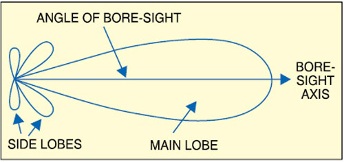
Fig. 1 shows the aperture of a typical antenna. Here BWΦ denotes the azimuth beamwidth and BWθ the elevation beamwidth. Beamwidth is normally measured at the half-power or -3dB point of the main lobe, unless otherwise specified.
According to the official website of the Antartic Impulsive Transient Antenna (ANITA, www.phys.hawaii.edu/~anita/new/papers/militaryHandbook/antennas.pdf), the gain or directivity of the antenna is the ratio of the radiation intensity in a given direction to the radiation intensity averaged over all directions. The difference between directivity and gain is that the directivity neglects antenna losses such as dielectric, resistance, polarisation and voltage standing wave ratio (VSWR) losses. Since these losses are usually quite small in most classes of antennas, directivity and gain are approximately equal, disregarding unwanted pattern characteristics.
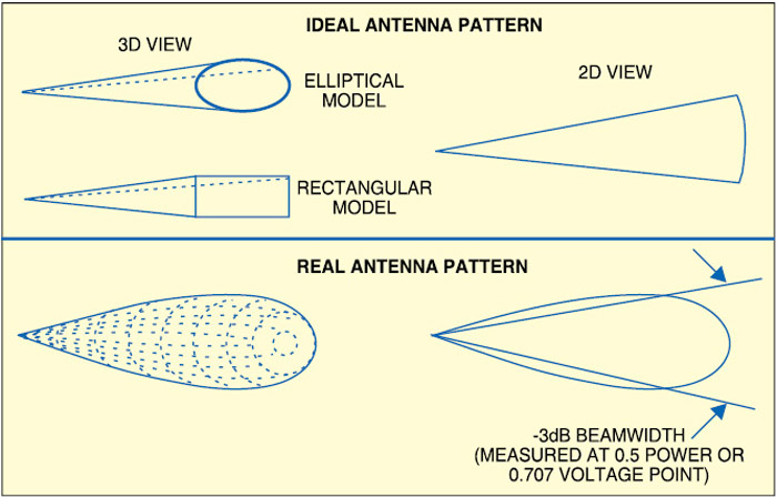
However, antennas are different practically, and do not have ideal radiation distribution. Energy varies with angular displacement and losses occur due to sidelobes.

If you can measure the radiation pattern, and determine the beamwidth, you can use two or more ideal antenna models to approximate a real antenna pattern as shown in Fig. 2. Assuming the antenna pattern to be uniform, gain G is equal to the area of the isotropic sphere divided by the sector (cross-section) area as:

Antenna efficiency is a factor that includes all reductions from the maximum gain. It can be expressed as a percentage or in dB. Several types of losses must be accounted for while determining the efficiency:
1. Illumination efficiency, which is the ratio of the directivity of the antenna to that of a uniformly illuminated antenna of the same aperture size
2. Phase-error loss or loss due to the aperture not being a uniform phase surface
3. Spillover loss (for reflector antennas), which reflects the energy spilling beyond the edge of the reflector into the back lobes of the antenna
4. Mismatch loss expressed as voltage standing wave ratio (VSWR), derived from the reflection at the feed port due to impedance mismatch—especially important for low-frequency antennas

No comments:
Post a Comment