A camera is one of the most powerful and accurate sensors if you know how to process the images taken by it for the information you want. You can process subsequent images and extract a variety of information using image-processing techniques. MATLAB is a very powerful tool and plays an important role in image processing.
Image processing is converting an image into digital form and performing some mathematical operations on it, in order to get an enhanced image or to extract some useful information out of it. Most image-processing techniques involve treating the image as a two-dimensional signal and applying standard signal-processing techniques to it.

Presented here is a MATLAB-based project where images taken by the camera are processed for colours and the position of a red-coloured object is extracted out of the image. Based on the position of the red coloured object in the image, different data are sent via COM port. The serial data are received by the robot and corresponding movement is done. You can change the code for any colour that you find suitable. This project is just an example and you can use this for various industrial applications such as controlling heavy load-lifting machines with some object of a specific colour in your hand.
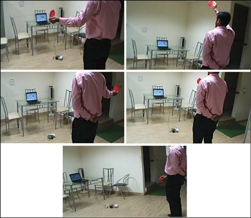
Coloured object can be held in your hand, which instructs the robot to move right, left, forward or backward as per the position of your hand, as shown in Fig. 1.
Circuit and working
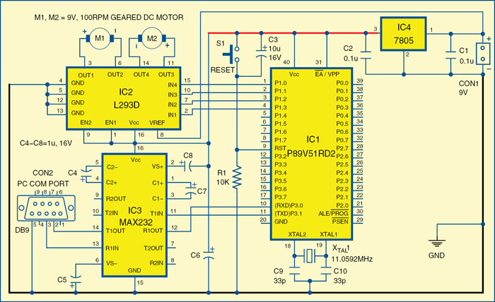
Fig. 2 shows the circuit of the robot, which uses microcontroller P89V51RD2 (IC1) to receive serial data from the computer through driver IC MAX232 (IC3). The received data is analysed by the microcontroller IC1 and the motors are controlled through motor-driver IC L293D (IC2). The power supply for the robot comes from a 9V battery which is regulated to 5V by regulator 7805 (IC4). 9V is also connected to pin 8 for IC2 for the motors.
Fig. 2 shows the circuit of the robot, which uses microcontroller P89V51RD2 (IC1) to receive serial data from the computer through driver IC MAX232 (IC3). The received data is analysed by the microcontroller IC1 and the motors are controlled through motor-driver IC L293D (IC2). The power supply for the robot comes from a 9V battery which is regulated to 5V by regulator 7805 (IC4). 9V is also connected to pin 8 for IC2 for the motors.

 The USB port of the computer is connected to the robot through USB-to-serial converter. Controlling commands to the robot are sent via serial port and the signal levels are converted into 5V TTL/CMOS type by IC3. These signals are directly fed to microcontroller IC1 for controlling motors M1 and M2 to move the robot in all directions. Port pins P1.0 through P1.3 of IC1 are connected to the inputs of IN4 through IN1 of IC2, respectively, to give driving inputs. EN1 and EN2 are connected to Vcc to keep IC2 always enabled.
The application running on the computer interprets the position of the coloured object and sends corresponding commands to the robot through the serial port. As shown in the pictures in Fig. 1, if the operator stands in front of the computer’s camera, holds a red-coloured object in his hand and raises his hand up, the MATLAB application running in the computer interprets the position of the coloured object and sends ‘a’ to the serial port. The robot is programmed to move forward if it receives ‘a’ from the serial port. Similarly, for other positions, the letters are listed in the table, which are sent through the serial port to the robot.

No comments:
Post a Comment