
Making of Thyristor Based CycloConverter and Its Applications
Cycloconverter is a frequency converter from one level to another, that can change AC power from one frequency to AC power at another frequency. Here, an AC-AC conversion process is done with a frequency change. Hence it is also referred as frequency changer. Normally, the output frequency is less than the input frequency. The implementation of the control circuit is complicated due to the huge number of SCRs. The Microcontroller or DSP or microprocessor is used in control circuits.
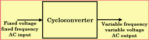
A cyclo-converter can achieve frequency conversion in one stage and ensures that voltage and the frequencies are controllable. In addition, the need to use commutation circuits is not necessary because it utilizes natural commutation. Power transfer within a Cycloconverter occurs in two directions.
There are two types of Cycloconverters
Step Up Cycloconverter:
These types use normal commutation and give an output at higher frequencies than that of the input.
Step Down Cycloconverter:
This type uses forced commutation and results in an output with a frequency lower than that of the input.
The cyclo-converters are further classified into three categories as discussed below.
Single phase to Single-phase
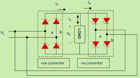
This Cycloconverter has two full wave converters connected back to back. If one converter is operating the other one is disabled, no current passes through it.
Three-phase to Single-phase
This Cycloconverter operates in four quadrants that are (+V, +I) and (−V, −I) being the rectification modes and (+V, −I) and (−V, +I) being the inversion modes.
Three-phase to Three-phase
This Cycloconverter is majorly used in AC machine systems that are operating on three phase induction and synchronous machines.
Introduction of Single Phase to Single Phase Cycloconverter using Thyristors
The Cycloconverter has four Thyristors divided into two Thyristor banks, i.e, a positive bank and a negative bank of each. When the positive current flows in the load, the output voltage is controlled by phase control of the two positive array Thyristors whereas, the negative array Thyristors are kept off and vice versa when negative current flows in the load.
The perfect output waveforms for a sinusoidal load current and various load phase angles is shown in Figure below. It is important to keep the non-conducting Thyristor array off at all times, otherwise, the mains could be short circuited via the two Thyristor arrays, resulting in waveform distortion and possible device failure from the shorting current.
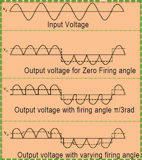
A major control problem of the cyclo-converter is how to swap between banks in the shortest possible time to avoid distortion while ensuring the two banks do not conduct at the same time.
A common addition to the power circuit that removes the requirement to keep one bank off is to place a center tapped inductor called a circulating current inductor between the outputs of the two banks.
Both banks can now conduct together without shorting the mains. Also, the circulating current in the inductor keeps both banks operating all the time, resulting in improved output waveforms.
Design of Cycloconverter using Thyristors
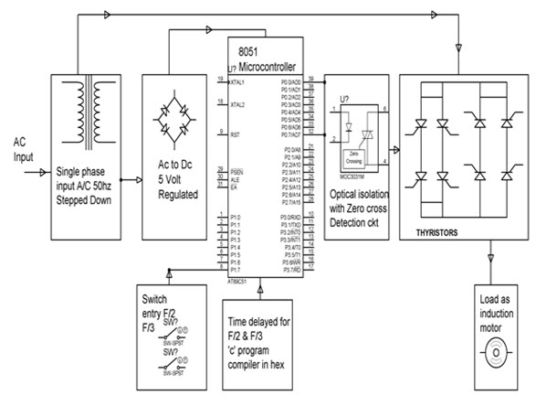
This project is designed to control the speed of a single phase induction motor in three steps by using a Cycloconverter technique by Thyristors. An A.C Motors have the great advantages of being relatively inexpensive and very reliable.


 Mumbai Academics Is Mumbai’s First Dedicated Professional Training Center For Training With Spoke And Hub Model With Multiple Verticles . The Strong Foundation Of Mumbai Academics Is Laid By Highly Skilled And Trained Professionals, Carrying Mission To Provide Industry Level Input To The Freshers And Highly Skilled And Trained Software Professionals/Other Professional To IT Companies.
No comments:
Post a Comment